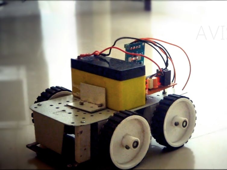
How to Make a Simple Homemade Rc Car
DIY Remote Control Car: The Best RC Car Tutorial
Remote control cars have been the dream toy for most kids. And you can never outgrow them! In this post, I will show you how to make one.
Intermediate Full instructions provided 4 hours 13,696
Things used in this project
Hardware components | |||||
| × | 1 | ||||
| × | 1 | ||||
 | × | 1 | |||
 | × | 1 | |||
|
| × | 1 | ||||
| × | 1 | ||||
| × | 1 | ||||
Hand tools and fabrication machines | |||||
 | |||||
Story
NOTE: The updated version of this article can be found here
Remote control cars have been the dream toy for most kids. And you can never outgrow them! In this post, I will show you step by step, how to make a simple Remote Control Car that operates in RF (radio frequency). This is a very simple and beginner level robotic project which can be made by anyone with interest. I will be discussing the working of all integrated circuits (IC) and modules used in this robot. And there is no programming required for making this robot!
Watch the robot in action:
Stuff you need to make the robot (Rc Car)
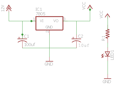
Make the power supply
First, we will start with the power supply circuit. Both RF transmitter and receiver circuit need a separate power supply. The receiver circuit need to powered using 12v supply and transmitter circuit can be powered using 9v battery:
PIN DESCRIPTION OF 7805 IC
- Pin 1 — Input voltage (5v-18v ) [V in]
- Pin 2 — Ground [gnd]
- Pin 3 — Regulated Output (4.8v – 5.2v]
- IC 7805 which regulates the 12v supply to 5v (if cant get a 12v supply you can use a 9v supply)
- 0.1uf & 470uf capacitor
- And 1k resistor for status led
NOTE: Use heat sink for 7805 because we are dropping 7v (12-5 )so lots of heat will be produced to burn the regulator so use heat sink is recommended
What is RF module?
This RF module consists of an RF Transmitter and an RF Receiver. The transmitter/receiver (Tx/Rx) pair operates at a frequency of 434 MHz. An RF transmitter receives serial data and transmits it wirelessly through RF through its antenna connected at pin 4. The transmission occurs at the rate of 1Kbps – 10Kbps. The transmitted data is received by an RF receiver operating at the same frequency as that of the transmitter. The RF module is used along with a pair of encoder and decoder. The encoder is used for encoding parallel data for transmission feed while the reception is decoded by a decoder. HT12E-HT12D
Working of the Robot
The RF module is used along with a pair of encoder and decoder. The encoder is used for encoding parallel data for transmission feed while thereception is decoded by a decoder. HT12E-HT12D
Pin Description of the RF Transmitter
- Pin 1 — Ground [GND]
- Pin 2 — Serial Data Input Pin [DATA]
- Pin 3 — Power supply; 5V [Vcc]
- Pin 4 — Antenna output pin [ANT]
RF Receiver
- Pin 1 — Ground [GND]
- Pin 2 — Serial data output pin [DATA]
- Pin 3 — Linear output pin (Not connected) [NC]
- Pin 4 — Power supply;5v [Vcc]
- Pin 5 — Power supply;5v [Vcc]
- Pin 6 — Ground [GND]
- Pin 7 — Ground [GND]
- Pin 8 — Antenna Input pin [ANT]
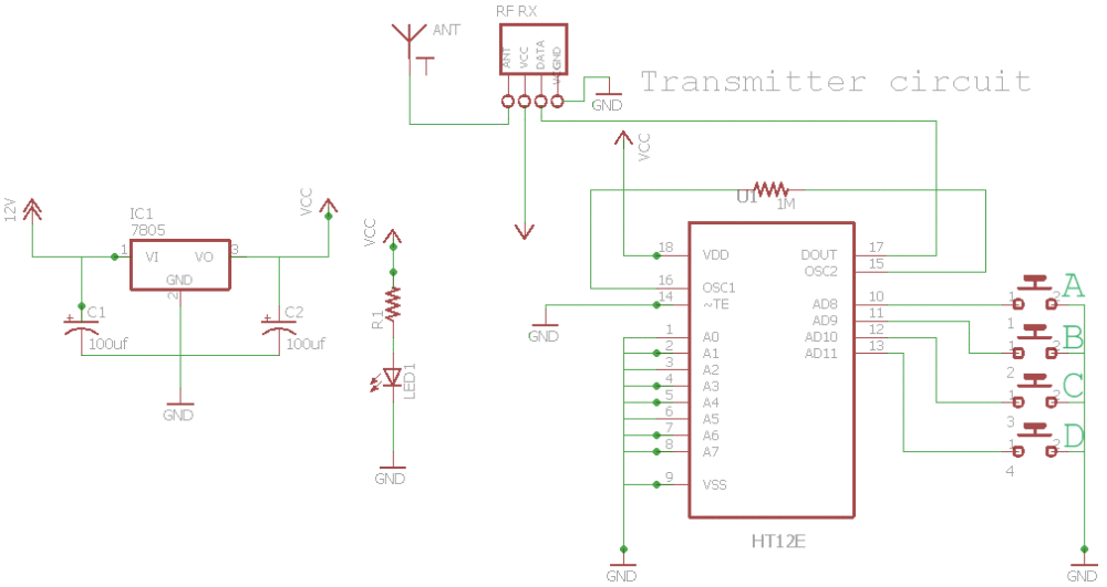
Make the Transmitter (Remote)
The transmitter circuit consists of:
- HT12E encoder
- RF transmitter module
- Two DPDT switch
- and 1M resistor
You can see I have marked A, B, C, D in the transmitter circuit after the switch and see the DPDT connection diagram below there also you can see I have marked A, B, C, D. Connect A,B,C,D on the transmitter circuit to A,B,C,D on the 2 DPDT switch. The DPDT switch connections is shown above.
HT12E Pin Description
- Pin (1- 8) — 8 bit address pin for output [ A0,A1,A2,A3,A4,A5,A6,A7 ]
- Pin 9 — Ground [ Gnd ]
- Pin (10,11,12,13) — 4 bit address pin for input [ AD0,AD1,AD2,AD3 ]
- Pin 14 — Transmission enable, Active low [TE]
- Pin 15 — Oscillator input [ Osc2 ]
- Pin 16 — Oscillator output [ Osc1 ]
- Pin 17 — Serial data output [ Output ]
- Pin 18 — Supply voltage 5V (2.4V-12V) [ vcc ]
- A0-A7 — These are 8-bit address pin for the output.
- GND — This pin should also be connected to the negative of the power supply.
- TE — This is the transmission enable pin.
- Osc 1,2 — These pins are the oscillator input and output pins.This pin is connected to each other with an external resistor.
- Output — This is an output pin. The data signals are given out from this pin.
- Vcc — The Vcc pin connected to the positive power supply, It is used to power the IC.
- AD0 – AD3 — These are the 4-bit address pins.
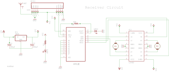
Receiver
The receiver circuit consists of 2 IC (HT12D decoder, L293D motor driver), RF receiver module.
Wire the circuit as per the above receiver schematic. There is 2 led in the receiver board, one lights up when thepower supply is given to the receiver and the other when thepower supply is given to transmitter circuit the led near the IC HT12D should lit and this provides you a valid transmission (VT) when power is given at the transmitter if not there is something wrong with your connection or your RF TX RX module.
Note: Use red wire for positive and black for negative if there is any problem with the circuit it will be easy for debugging the circuit
Pin description for HT12D VDD and VSS: These pin are used to provide power to the IC, Positive and Negative of the power supply respectively:
- DIN: This pin is the serial data input and can be connected to an RF receiver output.
- A0 – A7 : This is the address input . Status of these pins should match with the status of address pin in HT12E (used in the transmitter) to receive the data. These pins can be connected to VSS or left open
- D8 – D11: This is the data output pins. Status of these pins can be VSS or VDD depending upon the received serial data through pin DIN.
- VT: stand for Valid Transmission. This output pin will be HIGH when valid data is available at D8 – D11 data output pins.
- OSC1 and OSC2: This pin is used to connect external resistors for the internal oscillator of HT12D. OSC1 is the oscillator input pin and OSC2 is the oscillator output pin
- L293D (Motor Driver) The L293D is a Motor Driver IC it allows the motor to drive on both directions. L293D is a 16-pin IC with eight pins, on each side, dedicated to the controlling of a motor which can control a set of two DC motors at the same time in any direction. With one L293D we can control 2 dc motors. There are 2 INPUT pins, 2 OUTPUT pins and 1 ENABLE pin for each motor. L293D consists of two H-bridge. H-bridge is the simplest circuit for controlling a low current rated motor.
Pin description of L293D
- Pin 1 — Enable pin for motor 1 [Enable 1 ]
- Pin 2 — Input pin 1 for Motor 1 [Input 1 ]
- Pin 3 — Output pin 1 for Motor 1 [Output 1]
- Pin 4,5,12,13 — Ground [ GND ]
- Pin 6 — Output Pin 2 for Motor 1 [ Output 2 ]
- Pin 7 — Input pin 2 for motor 1 [ Input 2 ]
- Pin 8 — Power supply for motors(9-12v) [Vcc]
- Pin 9 — Enable pin for motor 2 [ Enable 2 ]
- Pin 10 — Input pin 1 for motor 1 [Input 3 ]
- Pin 11 — Output pin 2 for motor 1 [Output 3]
- Pin 14 — Output 2 for motor 1 [ Output4 ]
- Pin 15 — Input 2 for motor 1 [ Input 4 ]
- Pin 16 — supply voltage; 5V [ Vcc1 ]
Choose the right motor
Choosing a motor is very important and it totally depends on the type of robot (car) you are making, if you are making a smaller one use 6v Bo motor. If you are making a larger one that needs to carry heavy load then use a 12v dc motor.
Choose the right RPM for motor
I have 12V 300 RPM motor RPM, which stands for revolutions per minute, it is the number of times the shaft of a DC motor completes a full spin cycle per minute. A full spin cycle is when the shaft turns a full 360°. The amount of 360° turns, or revolutions, a motor does in a minute is its RPM value. You should be very careful while choosing the rpm. Don't choose motors of higher rpm cause it will be difficult to control it and remember SPEED IS INVERSELY PROPORTIONAL TO TORQUE DEBUGGING (OPTIONAL, if there is a problem with the circuit).
In this session, I will be discussing on debugging the circuit. First of all, don't be angry, just keep calm. For debugging we will split the circuit into different parts. First, we will be debugging the L293D IC. Place the IC on a breadboard and give 5v and Gnd to the IC and then give the 12v to pin 8. Connect the enable pins of the motors to 5v. Now give power to the input of one motor and check the output pins with a multimeter. If it shows nothing then there is a problem with your motor driver.
Power Supply
Most of the problems that arise in the power supply circuit are due to theshort circuits so for checking power off the circuit use a multimeter to check whether there is any connection between negative and positive.
Decode and Encoder (HT12E/Ht12D)
For debugging the decoder and encoder IC connect pin 7 of HT12E to pin 14 of HT12D. Connect push buttons at pin 10, 11, 12, 13 of HT12E and connect 4 LEDs at pin 10, 11, 12, 13 of the decoder (connect as per Decoder and Encoder Debugging circuit [fig 3]). The LEDs should light up when switches are pressed. If your robot is still not working then there would be a problem with the RF module and so try replacing the module.
Check out my blog for my new projects
If you have any doubt leave a comment here. It's my blog. I will be regularly checking for feedback there rather than here.
Schematics
Credits
How to Make a Simple Homemade Rc Car
Source: https://www.hackster.io/mayooghgirish/diy-remote-control-car-the-best-rc-car-tutorial-5a8ab2
0 Response to "How to Make a Simple Homemade Rc Car"
Post a Comment